Assignment 1 – Multiple Metal Shaping
Throughout the whole semester, by undertaking the Digital Making course allow me to explore varies ranges of aluminum sheet shaping techniques. On Assignment 1, we were allowed to exercise different shaping technique through making different shapes. It requires different shaping techniques and knowledge to successfully form the shapes of aluminum. It also helps me to get familiar with the modeling machines in the workshop and the metal shaping tools, which allows me to easier to get started in Assignment 2, the fuel tank modeling and even in the future.
Assignment 2 – the Fuel Tank
This reflection mainly focusses on reviewing modeling the fuel tank. This whole assignment is based on the knowledge and technique learning from Assignment 1 and applies the learning on the fuel tank modeling. It also requires us to learn different software by ourselves, in order to create a digital 3D model by using images and create a physical model template with the 3D model. Overall, this assignment is tough and fun at the same time. It takes multiple preparation and self-learning from scratch and applying the techniques on modeling, but it was also a fantastic opportunity to explore something I have never learned before by combining digital modeling & physical crafting to achieve organic shapes that are similar to the real selected model.
Review of Digital Making Progress
The entire Assignment 2 crafting progress can be found under the link over here.
I reviewed the entire process of this assignment and concludes the summary of digital making & what could be improved during the process. This summary applies not only the fuel tank but also on all the digital making – from real model to similar metal shapes.
Stage I: Digital 3D Modeling
The first stage is about creating 3D modeling from a real physical model. This requires the tools like camera, laptop and the good connection to the internet to access different software.

Tools required for digital modeling
The first software required is Recap by AutoDesk. This is an app specializing in photogrammetry for easy 3D modeling. It is downloadable from the Autodesk website for laptops.
Step 1:
The first thing is needed to do is to find a good object to model. Ideally, the model requires a shape that is possible to model by using metal shaping tools, which means the model cannot be too small or too over-decorated.
Also, the surface of the model requires to have easily recognizable colors & textures and low reflectance and shadows. Otherwise, the 3D modeling generator might not recognise the surface of the model.
After selecting the model, you need to take multiple pictures of the model from different angles. More of the pictures you take, more accurate the model would generate. Just make sure you keep the object still and in good lighting condition. Lay it flat on a mono-colour background. Avoid too much reflection & overexposure when you start taking photos.
Review:

During this step, I and my group members were quite rush to get the photos.
- We used a smartphone to take pictures, which the quality is not as good as cameras.
- We took around 20 photos of the model with workshop background, where we should take more photos in a white-colour background condition in order to get a more accurate 3D model.
- The lighting from the workshop is also quite overexposed, which we should do with gentle natural lighting.
Step 2:
After having enough amount of photos, upload them to AutoDesk Cloud and wait for the 3D model to be generated. Normally it takes multiple hours.
Step 3:

After the model is finished, the AutoDesk would send you an email with the generated model, which you would need later to create a laser-cutting template.

Open the model with AutoDesk Recap, you can then add in the real dimensions of the model, soften lumpy surfaces and erase unwanted areas.
Step 4:

Import the refined model into Fusion 360 with Slicer. It turns the 3D model into an assembled template with multiple 2D plans. The templates could be through a variety of construction methods, material type, and thickness, depending on your preference.
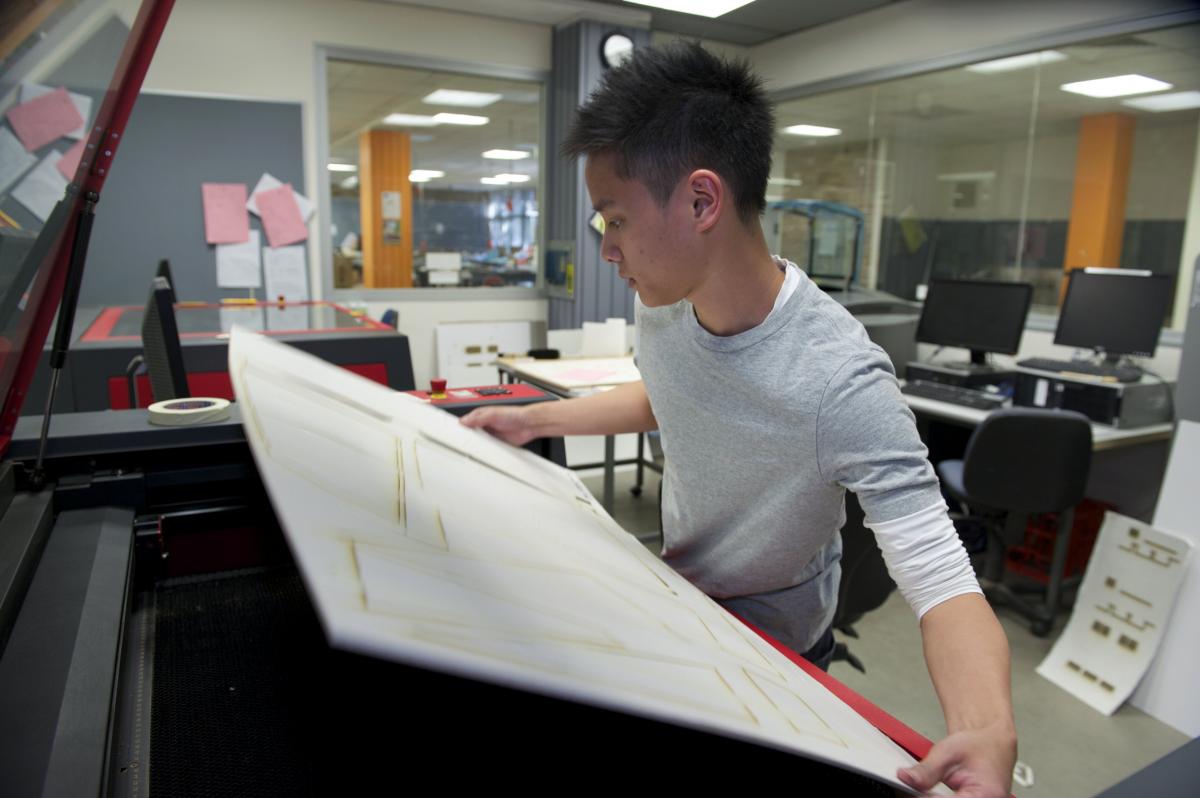
Stage II: Laser-Cutting & Assemble
The second process includes laser-cutting the template pieces created from the 3D model. This requires Adobe Illustrator, the material/sheet to be cut (ideally plywood thk. 3mm/6mm), lightweight hammer, and access to the laser cutters.
Step 1:
After deciding on which method and material to use, you will then need to modify line weight & line colour of the template files on Adobe illustrator. The line weight needs to be set to 0.001pt, and colour to be blue lines (engraved) or red lines (cut through).
Step 2:
After refining all the templates plans for laser-cutting, book a schedule of laser-cutting in the lab. An important thing to notice is the schedule is easy to get full, so manage your time well before submission. Also, each student can only use laser-cutting for 1 hour per week, so discuss with your teammates well.
Then upload these files on the laser-cutting lab computers. You will need to modify the printer settings according to your material/sheet (in this case is plywood 6mm) then start cutting.
Review:
On this step, our group did quite well, as we started booking laser-cutting a week before so we have ranges of selectable schedule to cut. we split the template sheets for 2 people, booked 2 laser-cutting machines and cut at the same time and the cutting finished within an hour.
Step 3:
After collecting all the template sheets, follow the assembly instructions in Fusion 360 Model and assemble the parts together. Taking care of the interlocking gaps might be a bit tight, which requires a lightweight hammer to force them to join together. The width of the gap can be modified in Fusion 360 earlier.
Review:

On this step, we should modify the width of the gap on the earlier stage in order to assemble the pieces easier. As a result, we have to use melee to hammer the pieces together. Once the pieces are hammered, it would be nearly impossible to take apart, so hammer with caution, make sure the gaps match the correct ones.
Stage III: Pattern Making
The next process is the pattern making. Basically, it's the process to divide the model into 3 parts, each part for each member of the group. This stage requires us to make the template into filled, smooth surfaces in order to divide the areas. It requires clear wraps, masking tape, marker, scissors, A3 Size Paper.
Step 1:

Use clean wrap to cover the model up to get a smoother and enclosed surface.
Review:

The original feedback from the tutors is to use masking tape to cover up the model, but after discussion, we find out clean wrap is a better option. It's cheaper and easier to wrap the model. The result is also smoother.
Step 2:

We then used paper to layer over to divide the model and get an approximation of the dimensions of the panel that each of us is going to shape.
Review:
On this step, again, we were a bit rush to separate the panels. The panels were not divided evenly, the edge of the panel is also not refined with much discussion. If we had more time on pattern making maybe we can divide the parts require the least amount of severe changes curvatures, which would make the metal shaping much easier.
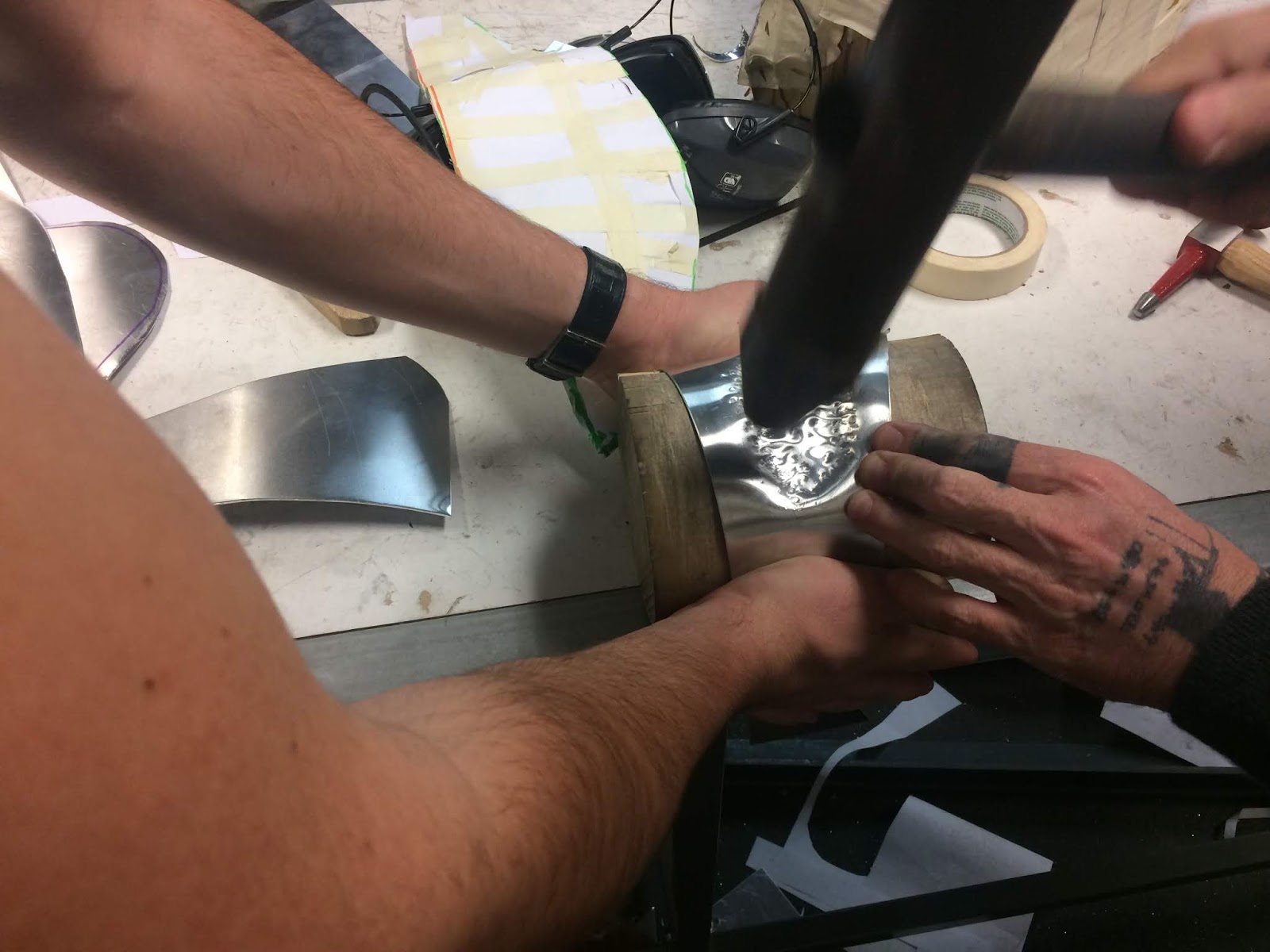
Stage IV: Metal Shaping
The next process is the metal shaping process. Basically, it is physically shaping an aluminum sheet to adhere to the contours of the 3D template. This requires access to the workshop tools like the melee, dollies, shot bags, metal cutters, etc.


Step 1:

When I was making the shape, I treated the shape as an irregular bowl, so I mark out the deepest point of the shape for hammering.
Review:

Work by Feimo Song
After reviewing some of my classmates work by Feimo Song, I found out my thought was quite wrong. I thought the shape have only 1 deepest point, but as the whole shape is curved, the deepest is not a single point but a whole area. As shown in his diagram, the centre area is curved the most, and the whole piece is actually curved in 3 directions. Hence, this shape is more like a combination of The Bowl and The Torus. If the shaping area is treated like this way, the shape would be much easier to make and more accurate.
Step 2:

Hammer the marked area to get an initial shape.
Review:
This step also has some problems. After reviewing Amity Leigh Yore & Feimo Song, who both were doing the side of the fuel tank, I found out they both started to getting initial shape by curving the whole piece first.
This step also has some problems. After reviewing Amity Leigh Yore & Feimo Song, who both were doing the side of the fuel tank, I found out they both started to getting initial shape by curving the whole piece first.

This initial approach helps them get the concave shape easily at the beginning stage, and as the result, it would be much easier and faster to follow the contour of the model template.

Curve the whole shape.
As I mentioned above, this step should be done before Step 2. This results in the initial shape became flat again and I have to refine the shape between step2 & step 3 again and again.
Step 4:
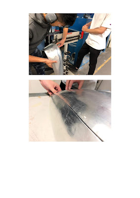
Repeat Step 2 & 3, comparing the shape multiple times with the model template.

The finished model
As I was too rush to finish the model, I did not continuously compare the shape with the model template as I was tapping. The shape was also treated without caution, left numerous hammer marks with heavy melee which could not be removed. As I reviewed Eu Gene Hyun's work, who is in the same group with me to shape another side of the fuel tank, told me she used a lightweight hammer to tap softly, with continuous comparing with the template. Also, she used English Wheel a lot to smooth the surface, which makes her model much smoother and shinier. It takes quite some time, but the result worth the time.

Comparing Gene's work (left) & mine (right)
Step 5:
Join the parts together and cut off unnecessary edges.

Review:
This step I think is the most important step that we missed. Under Feimo Song's blog, he mentioned after he finished his work, he also helped his group mate who is doing the piece adjacent to his piece. As the refine and work out together, the overall fuel tank result is quite impressively fit together. However, my group were only doing individual works, so the overall result did not come up very well as it left multiple gaps when they join together.
Song's refinement with his group mate.
Stage V: Polishing & Finishing Up
On the last stage, we find out the surfaces are quite lumpy. We decided to polish the surface to remove the hammer marks & scratches. Though it does not remove all the marks, it does refine the surfaces.
The tools need to be used is wipe & silver polish.

Overall Review:
As I get to know my classmates' working progress, I found out they really arrange their time well, treat the shaping with more caution and spend much more time to refine the result. And most importantly, works as a group to help each other out, in the end, it would achieve a much better result.


